Single
This is Hornresp’s main function, simulating horns. It has a wide assortment of different horn types to chose from, as seen here:
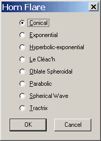
You can get to this window by selecting the Nd setting, blacking out all data in S1-S5 & L12-L45, and double clicking the L12 input block.
All of these horn types are a little different, and will alter the Cir & F# cells to allow you to work with the different profiles. All but Conical, Exponential, and Parabolic can only be used as a single segment horn.
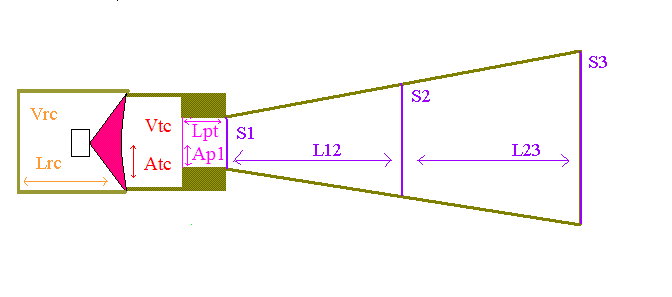
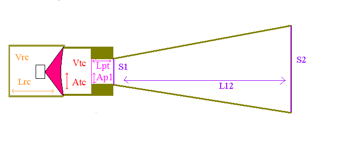
They all follow the same basic profile as shown in the picture below. Ap1/Lpt and Atc/Vtc can be left out if they are not needed, but the rest will be needed for every Nd front loaded horn.
I will go over the Hyperbolic flare horn design work flow here as an example. Start off with a blank slate, and select the HYP flare parameter by either double clicking the L12 block, and choosing form the list, or clicking the L12 block and pressing the “H” key.
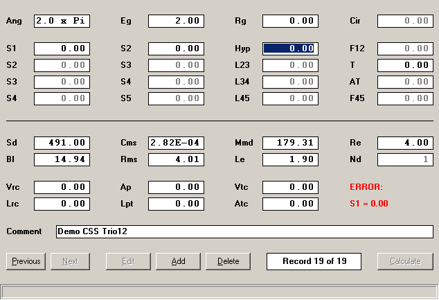
Now just enter a number into the L12 block, say 500 to lock the HYP profile in.

You must now input a preliminary horn. Take the Sd/2 and enter it as S1. Then take the Sdx10 as the S2.
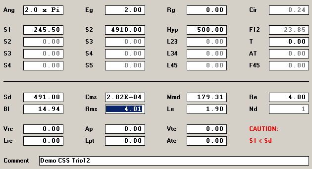
If you look at the Cir parameter it now says “.24” This is the distance of the parameter circumference of the S2 mouth when compared to the horns cutoff frequencies wavelength. I this case the mouth circumference is only .24 or 24% of the cutoffs WL.
The frequency cutoff in Hz is given by F12. This is the frequency at which your horn stops loading the driver.
Notice the red “Caution” that popped up. It is telling you that your driver will not mate up the the horn as it is. This means you need to add a Throat Adapter, which also means a Throat Chamber is created.
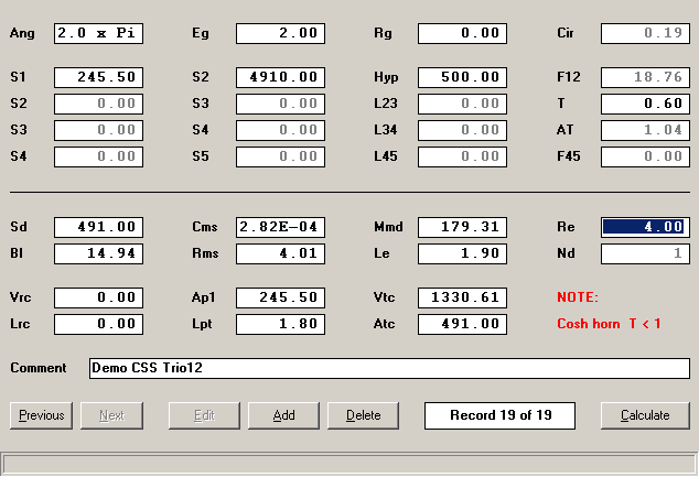
Go to Tools>Chamber and select the Throat Adapter. Ap1 will be the same as S1, and Lpt will the the thickness of the wood. Let’s use 1.8cm here.
The Throat Chamber is a little more tricky, but we can guesstimate. Use the drivers Sd as the Atc, and then try to figure out the distance between the drivers cone base, and the top of it’s flange/gasket, then divide it by 3. Using the PDF for this driver I get ~2.72. Remember this is only a fast guess, it would be better to measure the actual dish cc. Take the guessed 2.71 x Atc, and that is Vtc. Vtc=1330.61 This is just a starting point, as the size of the Throat Chamber affects the high frequency loading of the horn.
Now a red “Note” has popped up. This is the type of hyperbolic horn you are using right now, and a reminder to input a “T”. The T(it is referred to as “m” as well) is the slope profile of the horn, and is input where F23 use to be. Let’s use .6 for now.
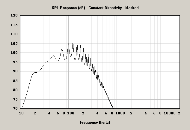
The single segment Nd horn will not allow the use of the Loudspeaker Wizard, so lets hit Calculate and check out the SPL Response. (Note: with Con, Exp, and Par you can cheat here by entering a second segment that is a sq cm more than S3, and ~1cm in length. This will allow you to enter the Wizard with no trouble.) Normally you would go ahead, and add the Rear Chamber before siming, but I want to show it’s effect there.
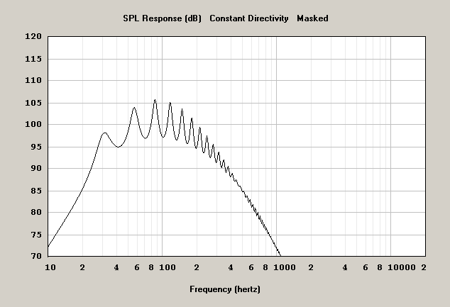
It is a bit bumpy. Let’s go back and enter a rear chamber. We will randomly use Vrc=30, Lrc=30 for now.
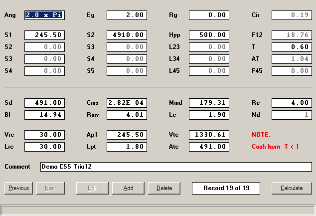
Then re-Calculate.
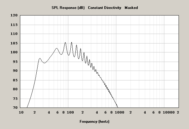
Now it is just a mater of playing with the parameters until you get the response you are after. This applies to all horn types. Each one will require different parameters to reach their potential, but that is beyond the scope of this thread. This will get you running though. 
Multi-Segmented
You can also do Multi-Segmented horns with the Con, Exp, and Par flare parameters.
It works exactly the same as the Single Segment Nd horns, only it does allow the Loudspeaker Wizard, so you can see the effects of your changes as you make them.
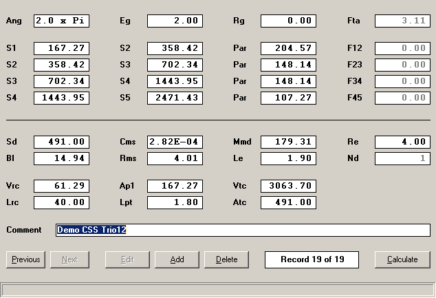
There is not a lot to add over the single section horn build. The main difference is that a “T” is not input as you are defining that yourself with the section Sd’s, so I will just give you a diagram and a sample segmented horn demo here.