Offset Driver Horns
Offset Driver horns are exactly like normal horns, only the driver is not placed at the true throat of the horn. It taps into the horn at a position further down stream from the throat.
You input and work with them in exactly the same way as a normal horn with one extra thing to check on. As the driver is not at the throat soundwaves are sent up and down the horn at the same time. This leads to cancellation issues above a frequency set by the round trip distance from the driver to the throat, and back to the driver. The longer the distance the lower the cancellation occurs.
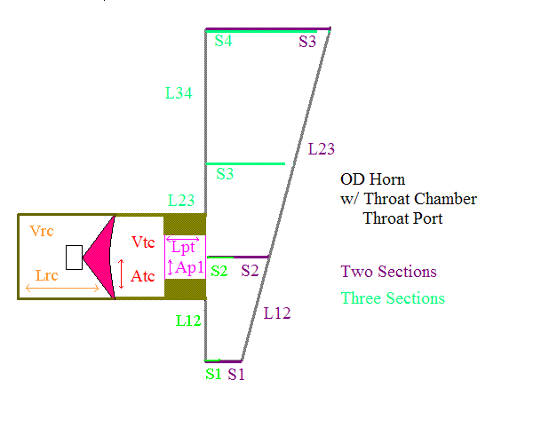
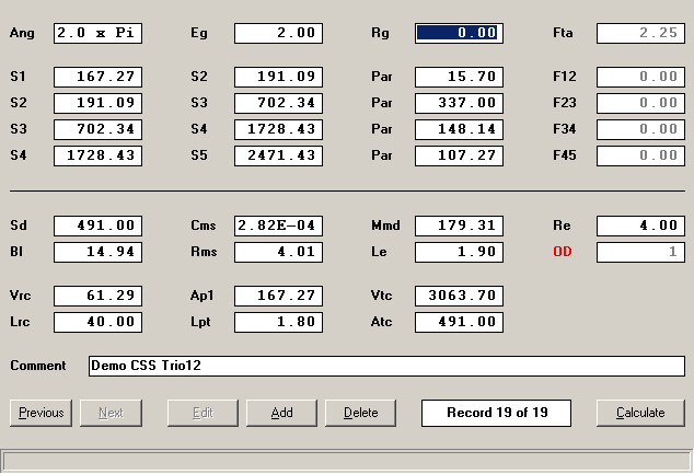
I am supplying a general parameter placement diagram, and the input screen of the same horn from the Normal Horns(Multi-Segmented) post, converted to an OD horn. This way it can be seen how they are similar, and how the cancellation effects the higher frequencies.
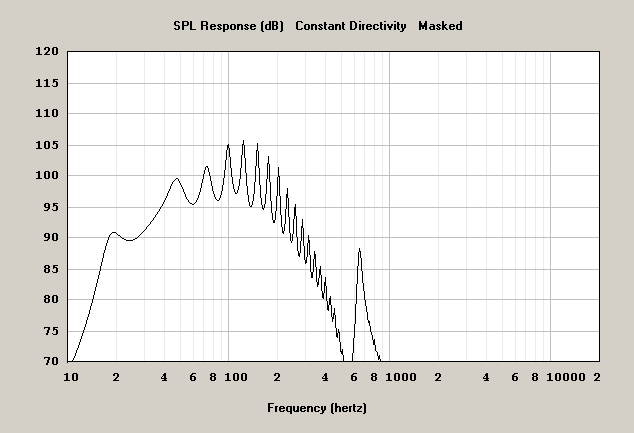
Tapped Horns
Tapped Horns are best though of as an extension of the OD Horn.
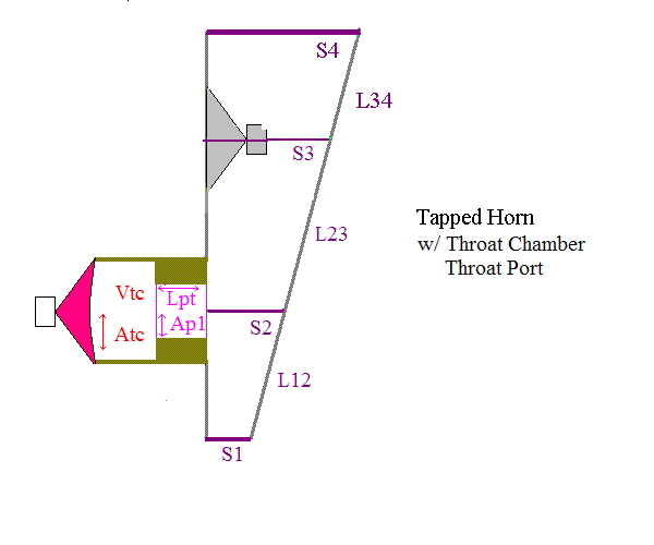
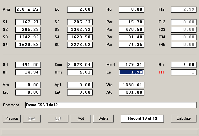
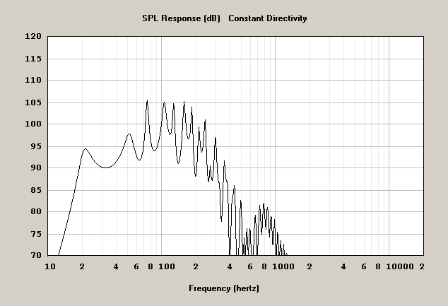
The key differences are that there is no Rear Chamber, and the second side of the driver taps into the horn as well. If you have made it this far reading straight through, there is nothing really more to add, as you should have no problems with the inputs. The Loudspeaker Wizard can be used with a TH setting.
Design parameters are out of the scope of this thread, but simply remember the length of the horn determines how low it will go, and the distance from the Rear Tap to the Throat is what fills in the dips, not the Rear Tap to Mouth distance. 
If you are flush mounting the driver you do not need the Vtc/Atc & Ap1/Lpt parameters.
If you are mounting the driver to the rear of the baffle/horn wall you will need at least the Vtc/Atc added.
Rear Loaded Horns
A Rear Loaded Horn is simply a Normal horn with no Rear Chamber. Really that is all it is. Instead of a Rear Chamber the driver is mounted externally, and you get the sum of the horn and drivers response.
To build one you do the exact same things as the Normal Horn builds (Simple or Advanced,) and just leave the Rear Chamber off. You must then use the Combined Response Graph to get the true FR.
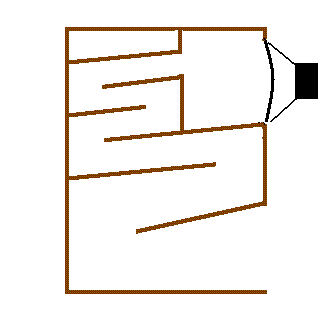
Note: Here I am using the cheat to allow the use of a single segment horn in the Loudspeaker Wizard.
Compound Horns
A Compound Horn is an enclosure with horn loading on each side of a driver. It is selected by changing the Default Nd to CH.
When you select this option there are several changes to the program. First S1-S4 the first three segments are set aside for the main horn, but you may us as little as one segment. You are also allowed a Throat Chamber for it Vtc & Atc, and a Throat Adapter for it Ap1 & Lpt.
The second horn is given the last segment S4-S5, and the Rear Chamber (Vrc & Lrc) becomes it’s Throat Chamber.
The loudspeaker Wizard is not allowed with this alignment. You must also use the Combined Response graph with this setup, and the default graph only shows the main horn output.
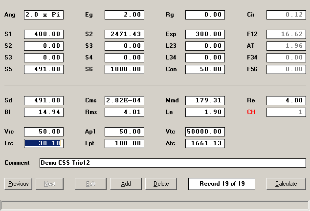
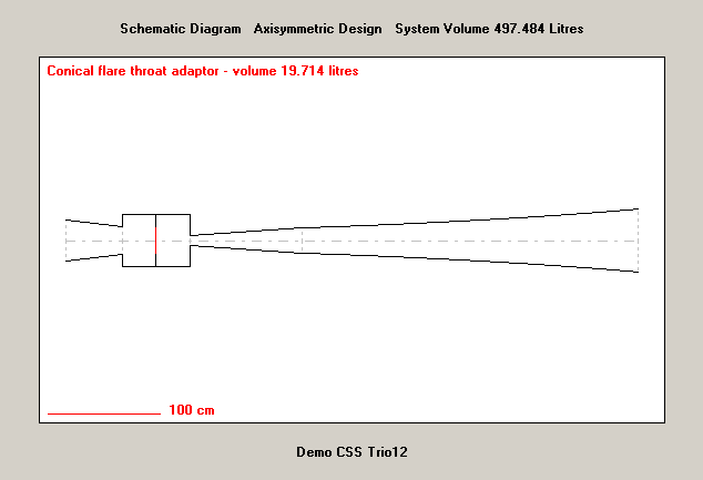
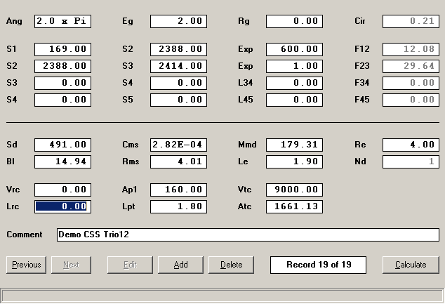
This is a pic that will allow you to get the feel for it, and identify the component locations with the schematic. The demo horn is not a good design by any means. It’s only purpose is to make the areas standout.